AUXILIARY POWER SOLUTIONS FOR EV CHARGERS
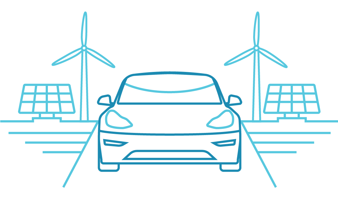
One of the biggest changes that is already under way is the move from fossil fuel vehicles to cleaner and more efficient electrically propelled vehicles (EV). While there is much work to be done within the vehicles themselves, the provision of a sufficient number of charging stations globally is challenging industry and governments. Range anxiety – the fear of becoming stranded – and the time taken to charge an EV are often cited as reasons that sales of EVs are lower than hoped for. Clearly, solving this challenge is going to have a huge benefit for automakers, the driving public, and the environment. In this technical article we will take a detailed look at the types of chargers being developed and rolled out and consider the power needs for each of the key features.
BACKGROUND
Some of the very first vehicles ever made were electric. However, that changed when the electric starter was invented. This brought internal combustion engine (ICE) vehicles to the forefront while electric vehicles were consigned to history. During the oil crisis in the early 1970s and the Californian Zero Emission Mandate during the 1990s, there was renewed interest in electric vehicles, but they did not become mainstream.
In recent years, new battery technologies have emerged. Coupled with widespread environmental concerns and a customer base seeking cleaner alternatives to fossil fuels, electrically powered vehicles are finally becoming a viable technology
The market is maturing rapidly but remains in its early stages and a variety of vehicle types are available. Hybrid vehicles contain both ICE and electric motors, which may be designed such that either one or both are used for propulsion. Pure battery types are wholly electric and reliant upon the charge stored in the battery to travel. Broadly speaking, the market can be split into two sections – the hybrid types that charge their own battery using the ICE(HEV, MHEV) and the types that can be plugged in to charge (BEV, PHEV).
As battery technology improves and EVs become more efficient, their range is increasing and starting to approach that of an ICE vehicle. Many of the most common journeys, like the daily commute, can be made without recharging. Nonetheless, range anxiety relating to making longer trips in an EV remains a hurdle, preventing many customers from adopting the new technology. When an ICE vehicle runs low on fuel it is simple and quick to refuel at a traditional gas station. Charging the battery in an electric vehicle, on the other hand, can take many hours depending upon several factors including the state of charge, battery capacity, charger type and so on. Clearly, in-journey charging of several hours is hugely impractical and so EVs are more frequently charged ‘at destination’ – whether that is a short top-up at the shopping mall, an all-day charge at the workplace, or overnight at home.
OVERVIEW AND MARKET FOR EV CHARGERS
The market for EV charging is driven by sales of EVs themselves and, more specifically, sales of the types that can be plugged in to charge – namely BEV and PHEV. According to a recent report by McKinsey & Company, the 8 million or so BEV and PHEV on our roads in 2020 will have grown significantly to around 120 million by 2030.
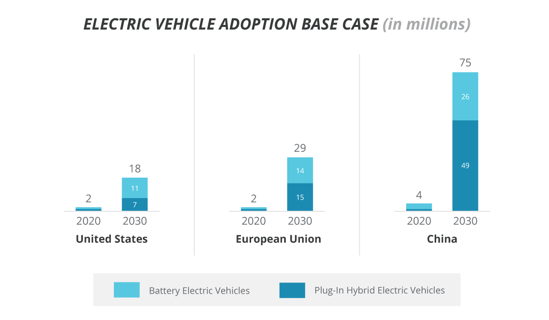
With 18 million BEV / PHEV in the US by 2030 and around 13 million chargers, there will be a charger for every 1.38 vehicles. In the EU, EV drivers will be somewhat less well served with 15 million chargers for their 29 million vehicles – one charger for every 1.87 vehicles – although the more compact geography may well go some way to making up for this.
If we use McKinsey & Company’s figure of 20 kWh per 100 km (~60 miles) then the 18 billion kWh of charging capacity required in 2020 will show a similar level of growth to 271 billion kWh by 2030, with a five-fold increase by mid-decade and a further tripling of demand in the latter half of the decade. While these figures are staggering, put into context, 280 billion kWh is around 8% of all energy demand in the US.
During the early stages of EV growth, most of the charging will be done at home, especially in the US and Europe. While the situation moving forward will depend upon many factors, there will be a gradual shift towards charging EVs at work, beside the highway, and other public spaces over time.
The types of chargers deployed will depend upon how the technology evolves, where the charging is done and, the available power at that location. While there is much discussion about the dc-driven ‘fast chargers’ that can recharge vehicles in minutes, due to the large installation and maintenance costs along with high power and voltage requirements, these are only viable in certain locations and will remain in the minority – especially in the US.
AC vs DC CHARGING
Given the different charging locations and power feeds, it comes as no surprise that there will be different types of chargers deployed. The primary delineation will be by the type of power supplied to the vehicle, and the power that is able to be delivered.
| Depiction | Charger Level | Power Ratings |
|---|---|---|
 |
1 | AC (120 V) Up to 1.9 kW |
 |
2 | AC (208 - 240 V) Up to 19.2 kW |
 |
3 | DC (600-1000 V) Up to 400 kW |
Within the industry several standards have emerged that define different levels of charging station. A common standard is SAE J1772, published by SAE International, which defines four charger levels:
- Ac level 1 specifies a 120 V ac voltage capable of up to 16 A or 1.9 kW
- Ac level 2 specifies 208 to 240 V ac voltage station capable of up to 80A or 19.2 kW
- Dc level 1 specifies a dc voltage up to 1000 V and 80 A or 80 kW
- Dc level 2 specifies a dc voltage up to 1000 V and 400 A or 400 kW
Dc levels 1 and 2 are often referred to jointly as level 3 or as dc fast chargers. Other standards exist which define similar but different voltage and power levels.
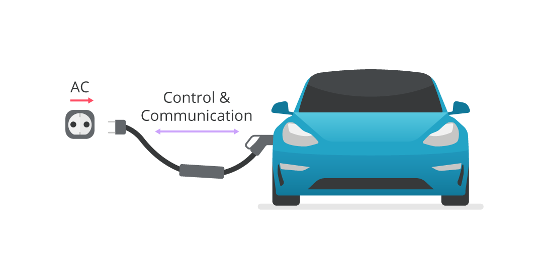
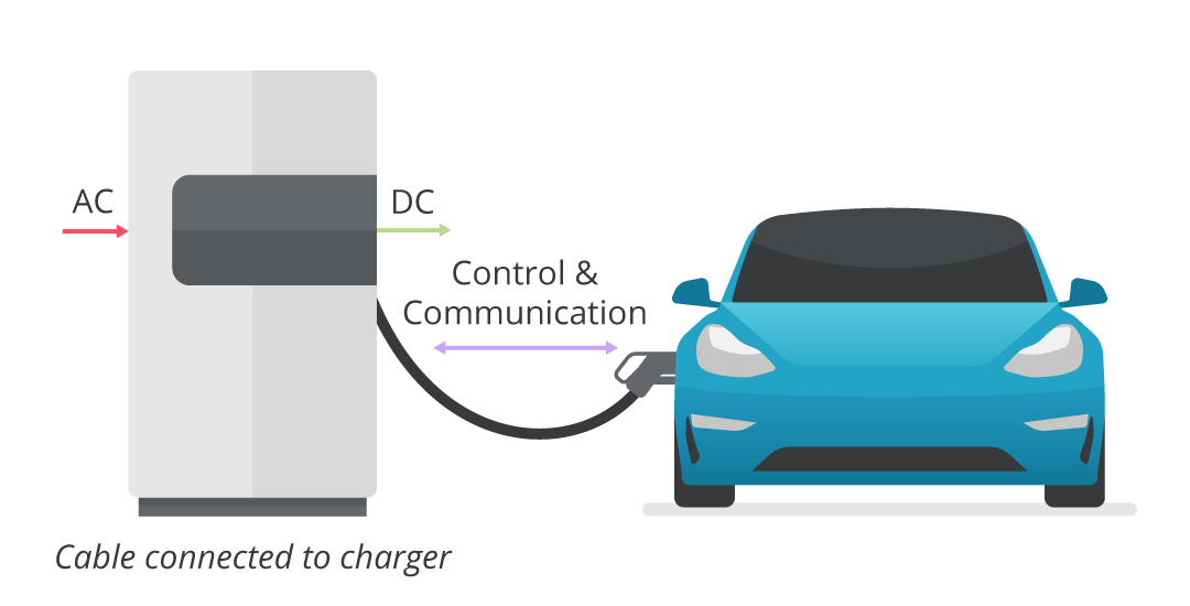
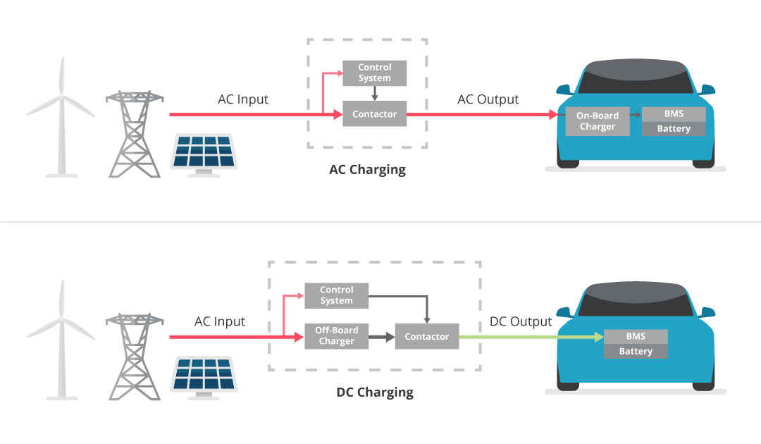
Batteries can only be charged by dc and mains grids are always ac so at some point in the electrical powertrain, a conversion (rectification) is required. With the higher-powered dc chargers, this conversion is done within the charging pile, meaning that dc power is supplied to the vehicle. This is normally fed directly into the battery management system (BMS) which then manages and monitors the charging of the battery.
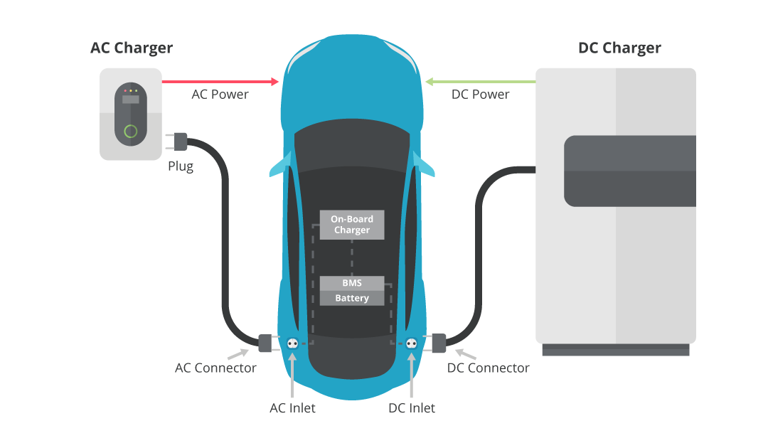
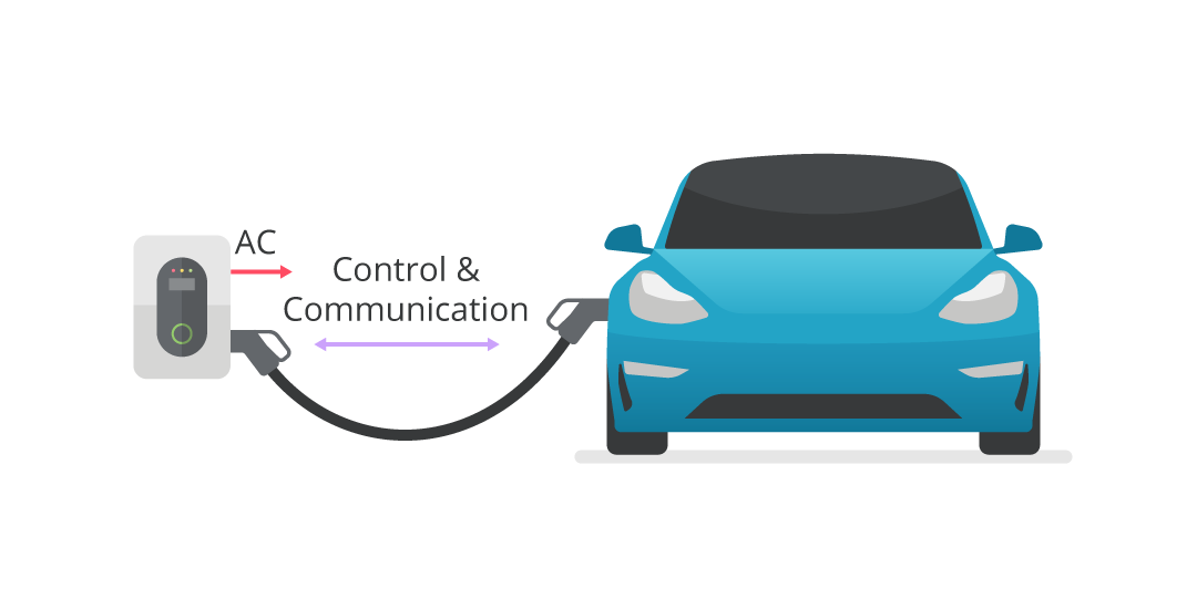
With ac charging, there is no rectification within the charging pile, so ac power is supplied to the vehicle. An on-board charger (OBC) then rectifies this voltage and, if necessary, changes the voltage level to be suitable for the BMS / battery string.
While ac charging piles are simpler and less expensive, the drawback is the need for the OBC as this adds weight to the vehicle, thereby reducing its range. With the very cramped spaces in modern vehicles, finding space to fit an OBC can be a challenge and in all cases, power density must be as high as possible. This can lead to operation at elevated temperatures which stresses components and, because the OBC (by definition) goes everywhere the vehicle does, the unit is subject to shock and vibration on every journey.
Dc charging piles do, in theory, remove the need for an OBC although, at least for now, most vehicles are OBC-equipped with a bypass function so the dc is not rectified needlessly. The inclusion of the OBC is useful in case the only available charging station within range is an ac pile.
Given the amount of energy stored in vehicles which may spend much of their time parked either at home or work, energy companies are sensing the opportunity to tap into this reserve power as a way of load balancing the grid, helping to reduce the need for additional power generation capacity. During times of peak demand / higher electricity cost, the vehicle would deplete its battery to power a home or contribute to the grid. When electricity prices fall, typically overnight, then the vehicle would recharge its battery, ready for the morning commute.
While in the early stages, using the energy stored in vehicle batteries requires a bidirectional charger / inverter that also allows power to be returned to the grid.
CHARGING STANDARDS AND CONNECTIVITY
As with almost all emerging technologies, a variety of competing standards exist for vehicle charging. Currently, there are three primary charging protocols available that cover the communication with the vehicle and the connector type.
- CHAdeMO (charge de move)
- Started in Japan in 2010
- Comprised of the main Japanese automakers including Honda, Nissan, Toyota, and some EU companies
- Protocols are based upon IEC6185 / IEC62196 including the definition of a standard-specific connector
- Currently, up to 400 kW / 1000 V is supported although a collaboration with the China Electricity Council (CEC) could push this to 900 kW
- Combined Charging System (CCS)
- Primarily US / European
- Includes Ford, General Motors, VAG, BMW and several Asian manufacturers
- Aligned with applicable IEC, SAE and ISO standards and supports ac charging (single- and three-phase) and dc charging
- Currently above 200 kW capability for dc charging, 350 kW protocols are in preparation
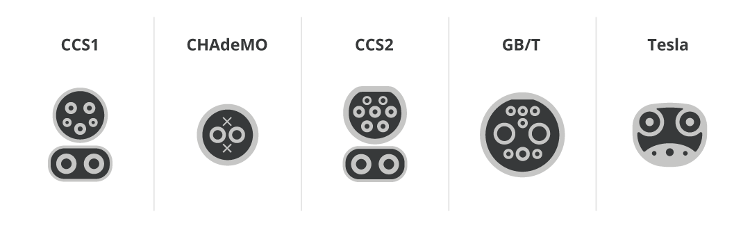
- CCS created their dc charging connectors (Combo 1 and Combo 2) by adding a two-pin socket for the dc currents to their original ac connectors, allowing both ac and dc charging via the same connector
- Tesla Superchargers
- Proprietary technology and primarily only for Tesla vehicles
- Currently deployed with peak power levels of 72 kW, 150 kW (both version 1 and version 2) and 250 kW (version 3)
- The connector is a proprietary solution in North America but elsewhere vehicles are supplied with adaptors for CHAdeMO or CCS
INSIDE THE CHARGING PILES
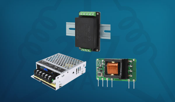
While the high-power path between the grid and the vehicle is the primary power conversion required within ac and dc charging piles, these sophisticated devices include a significant amount of control and protection circuitry that requires dedicated power solutions.
Essentially, both ac and dc charging systems are very similar, with the major difference being the location of the ac-to-dc conversion. An ac charger has a simple pass-through contactor, and the conversion is performed in the vehicle. In the case of dc charging, there is a large ac-dc converter embedded within the charging pile.
The simplest charging pile is the Level 1 ac charging unit, which primarily consists of a large relay to switch the charging power into the OBC on the vehicle. In terms of power rails, the primary rail is 12 V dc and typically comes from a miniature board mount ac/dc with external EMC circuitry to allow for a more compact design.
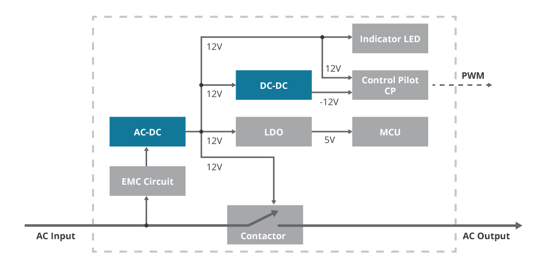
The control pilot, which communicates the charging status and monitors the protected earth connection, requires a +/-12 V dc supply. The positive rail comes from the ac/dc unit, and the negative rail can be generated with a small PCB mount dc-dc converter.
To power the microcontroller the 12 V rail must be stepped down to a lower voltage – here it is shown as 5 V dc, but it could also be a lower voltage depending upon the device selected. The voltage for the MCU can be generated in several ways. As no isolation is required, a small low-dropout regulator could be used (as shown) or equally a simple ‘buck’ converter (non-isolated point-of-load – NiPOL) could be used as a more efficient option.
Level 2 ac charging units tend to be more complex than level 1 units, with additional features and functions that result in the need for more auxiliary power. However, in level 2 chargers there is usually more space to work with, so the design can be simplified by using an ac/dc with an internal EMI filter.
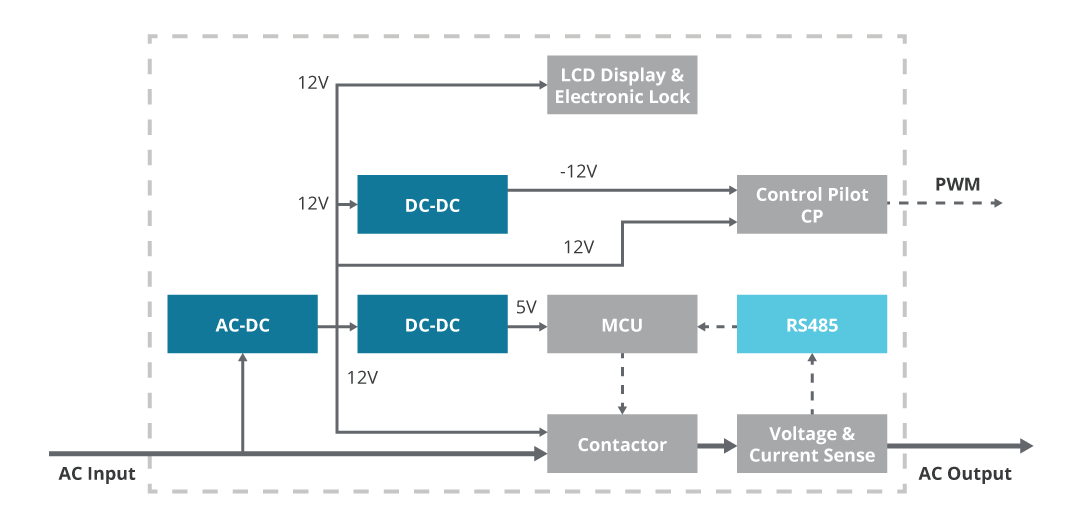
Downstream from the ac-dc, the solutions are much the same as before. A dc-dc generates the negative rail for the control pilot, but this time we have shown a dc-dc converter for the 5 V rail instead of an LDO, although either could be used.
The architecture changes somewhat when moving to the dc chargers. With additional features including security monitoring, control electronics, LCD display and measurement, as well as the need to power the BMS unit located within the vehicle, more power and more rails are needed.
Three-phase ac power is supplied to the charger, often at 480 V ac. The 150 W ac/dc’s that supply the auxiliary rails must have an extra wide input so they can run off the single-phase voltage of 277 V ac. At this power level, power factor correction (PFC) is a requirement and is included in each of the ac-dc power supplies. In the case of figure 8, the main auxiliary rail is 24V and supplies the controls, monitor, and display circuits. A second ac/dc supplies a 12 V rail that is fed directly to the BMS unit via the connector.
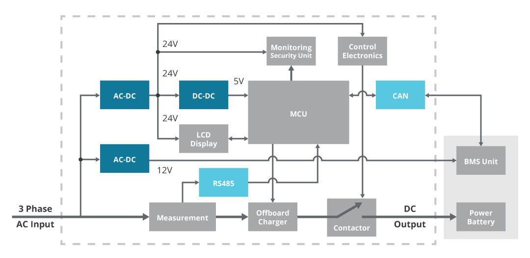
Again, the MCU requires a 5 V supply which is generated via a 5 V dc-dc converter directly from the 24 V rail.
In addition to providing the correct voltage, there are several other considerations which will affect the power solution used. In these densely-packed high-power systems, a high ambient is to be expected, especially when operating in a hot country. However, in winter in a cold country, the power solution may be required to start up correctly from a sub-zero temperature if the charging pile has been dormant for a while.
EMI performance is important and, when using off-the-shelf modules, this is a known quantity and repeatable. Especially with the Level 3 dc charger, surge performance is an important consideration, and this may necessitate the use of power supplies with increased surge immunity or the addition of protection circuitry within the power system.
In these examples we have shown typical arrangements for charging piles in each of the three levels. In practical applications, there will be differences and possibly more or less features. However, the principles for designing and selecting modular power supplies and converters for any charging pile remains the same.
SUMMARY
Clearly, the concept of electrically-propelled vehicles is back and this time it seems that it will be successful. However, there remain many challenges to overcome, not least defeating range anxiety and the time taken to replenish batteries – especially if this is necessary mid-journey.
Despite competing standards, EV charging piles are evolving rapidly and power delivery is increasing so that EV batteries are eventually able to be significantly recharged in just a few minutes. Within these power systems are a wide range of power needs, all of which can be addressed with off-the-shelf modules.